


A circuit board diagram is a pivotal tool in the electronics industry, serving as a blueprint for designing and constructing electronic circuits. These diagrams are essential for both professionals and enthusiasts alike, providing a detailed map of the connections and components that make up a circuit. Whether it's for an Arduino Uno circuit schematic or a complex communication device, these diagrams are the foundation of electronic design.
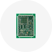
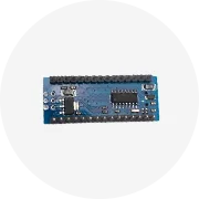
Circuit board diagrams come in various forms, each tailored to a specific type of project or application. For instance, an Arduino Nano schematic diagram is ideal for small-scale projects, while a pcb circuit diagram is more suited for intricate printed circuit board designs. Other types include the breadboard diagram, which is used for prototyping without soldering, and the circuit board schematic, which represents the circuit in a simplified form with standardized symbols.
The applications of circuit board diagrams are vast and diverse. They are used in designing consumer electronics, industrial machinery, and even DIY projects like the 3055 amplifier board 450w. For educational purposes, diagrams such as the schematic diagram for Arduino Uno help students understand the basics of circuit design and function. In more advanced fields, a circuit board drawing is crucial for the development of complex electronic systems.
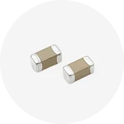
Circuit board diagrams are characterized by their detailed representation of connections, which can include various types of lines and symbols indicating components like resistors, capacitors, and integrated circuits. The materials referenced in these diagrams, such as copper for conductive pathways or fiberglass for the board substrate, are crucial for understanding the physical construction of the circuit.
Utilizing a circuit board diagram offers numerous advantages. It ensures accuracy in building circuits, facilitates troubleshooting by identifying each component and its connections, and aids in the replication of designs. For complex projects, such as an egs002 inverter circuit diagram, it provides an invaluable reference that guides the assembly process and ensures that the final product functions as intended.
The creation and interpretation of a circuit board diagram require a certain level of expertise. Tools like draw a circuit board software can assist in the design process, while knowledge of electronic symbols and circuit theory is essential for understanding the diagrams. For hobbyists, starting with simpler projects like a breadboard to circuit diagram conversion can be a great way to learn and develop these skills.


 浙公网安备 33010002000092号
 浙B2-20120091-4